Railway Point Control Circuit
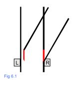
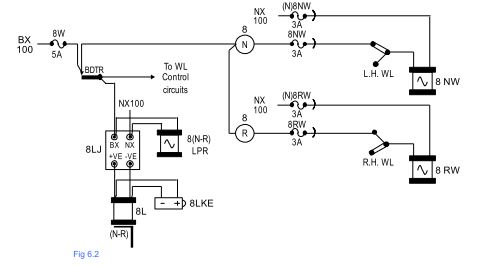
Point Control Circuit :- Fig 6.2 shows the Point Control circuit for a right hand turnout set of Clamplocks. The WL detection contacts are cut into the NW and RW control lines to prevent the WL being damaged by the drive lock slide pushing against the thin WL dab. The full retraction of the WL is proved by its respective bottom limit switch. The points shown laying normal in Fig 6.1 are a R.H. turnout.
If the points are thrown Reverse, the R.H. WL must be proved to have fully retracted by the bottom limit switch before an electrical feed is put onto the RW valve to throw the points over to the Reverse position. If they are thrown back to the Normal position, then the L.H. WL must be proved to have fully retracted by its bottom limit switch before an electrical feed is put onto the NW valve to throw the points back to the Normal position.
‘V’ Style Frame Clamplock Point circuits
Clamplock Point circuitry in many respects is very similar to the principles employed with Flat Bottom Four Foot point circuits. The areas of similarity are in the Lever Lock and WL Control circuits and do not differ from those discussed in section 9.4.1 Lever Lock circuits and section 9.4.3 WL Control circuits. These are shown greyed out in Fig 6.2. We shall take a look at the slight differences in the point control and detection circuits.
Detection Circuits
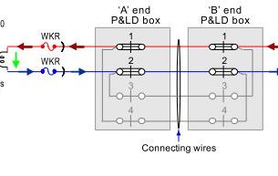
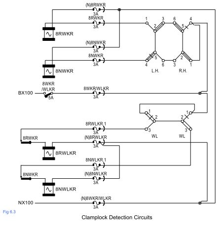
Fig 6.3 shows the detection circuitry for a R.H. turnout set of Clamplocks. Both limit switches in each Clamplock unit are detected in both the Normal and Reverse positions. These limit switches pick up their respective WKR. Both WLs are also detected. On the closed switch side the WL dab is detected to be engaged in the port. On the open switch, the dab is detected to be resting on the drive lock slide. These positions are detected by each WL’s respective top limit switch. The NWLKR or RWLKR contacts are used in the selection circuitry of any signals that route a train over these points.
Insufficient Track Locking
Track locking is a means of directly locking a set of points using their associated track circuit(s) to prevent them from moving while a train is on or approaching them. To achieve this, the points must be track circuited throughout their entire length and in the case of pneumatic points be fitted with a Ground Lock. Should a train enter the track circuit associated with the points at the very moment they are about to move, they must have fully completed their travel and locked by the time the train reaches the tips of the switches.