Railway Electromagnetic screening
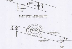
Induced voltage in the cable core
E = – ZI Kr Kc Km, where Z = j ω M and ω=2 π f
E = Induced voltage in Cable Conductor/KM
ω = angular frequency
Z= mutual impedance between OLE & S&T conductor per unit length (in ohms)
M = Mutual inductance between OLE & S&T conductor per unit length (in henries)
I = Catenary Current
Kr = Rail reduction factor
Kc = Cable Screening factor
Km = Mutual Screening factor due to presence of other cables, metallic bodies in the vicinity. This need not be considered while calculating the induced EMF, as there may not be any other metallic body in the vicinity.
CCITT limits
CCITT limits for Induced Longitudinal Emf.
Directives
1.5.6.1: To avoid danger to persons and risk of damage to cable and apparatus, the longitudinal emf arising in a telephone circuit from a short circuit in a power line with flow of current through earth should not exceed 430 V rms.
1.5.6.2: Longitudinal induced emf during normal operation of the power line should not exceed 60V rms Standard practice on B.R. is for all Telecom installations to comply with above recommendations.
Protection measures in Electrified area
- Electrical Clearances
- Whenever a ‑ high voltage conductor is provided, a minimum electrical clearance is required to be provided to safeguard against flashing/arcing. For 25 KV A.C. the electrical clearance is specified as 600 mm from the live conductor.
- Besides the above, in the matter of electrical clearances, the fundamental rule to be observed is that no one is allowed, under normal conditions, to approach closer than 2.75 metres from the extreme positions of the live parts of the OHE.
When the signals have to be so located that they infringe, in 2.75 m zone , a screen of wire mesh shall be provided between the signal post and the OLE to protect the staff who may have to work within that area.
- Visibility and Location of Signals.
- Signals should be so located that they their visibility is not affected by OLE masts, insulators, wires etc. and they have the visibility as required by the standards.
- Restrictions on minimum distance exist on placement of the signal behind the OLE mast and in front of the mast.
- Implantation of successive OLE masts in front of the signal is staggered, giving extra sitting distance.
- Earthing – Metallic sheath and armouring of all underground cables, signal structures, protection screen of signals, all Telecom equipments etc.
- Insulation.
– Traction Return Currents pass through rails and since rods and wires (in case of Semaphore Signalling) are in contact with the rails at some point or other, the rail voltage, which can be quite large in case of faults, is transmitted through them to the lever frame. Further the rods and wires in A.C. Electrified areas are subject to a certain amount of induced voltage.
– To protect the operating staff from the effects of the voltages mentioned above, the rods and wires are provided with insulation.
- Type of cables
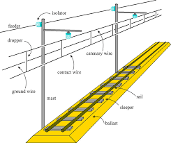
– In the vicinity of 25KV A.C. electrified section, no aerial lines are permitted to be used as they are subjected to Electro-static induction. Hence, all the circuits are transferred to underground cables.
- Special precautions in laying of cables.
- Traction current contamination.
Use of traction immune signalling equipment, such as point machines, track circuits and relays.
E.g. for Point operation and detection.
Use of permanent magnet type Electric point machines, of type BS 581 and BR specification 902, that provide immunization.
Point detection and point detection repeat circuits are normally of polarized type, with detection relays to BR specification 932 A 50V operating, which are fully immunized to a.c.
Point control relays – BR 943 or 966, which are fully immunized to a. c.
- Induction from parallel a. c. or high frequency circuits.
- Use of dc feeds and ac immune relays for external circuits.
- Limiting length of through connected conductor parallel to the railway, such the maximum induced current would be insufficient to operate any a. c. circuit.
- Length of circuits.
Signalling Line circuits
- Length of any signalling line circuit must be limited to ensure that induced voltage from traction system, does not exceed 110V under normal conditions and 430 V under traction fault conditions.
- If necessary, line circuits must be sectionalised.
- Maximum permitted length of through connected conductor is 2000m.
- Trackside circuits.
Distance between signal and its signal control relays should not exceed 200 m.