Railway Bonding Plan & Track Plan
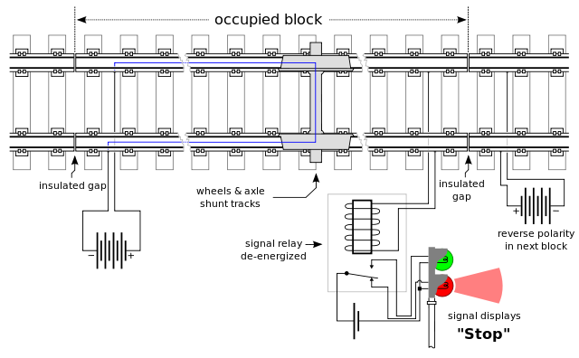
The majority of running rails are used to form track circuits to provide a means of proving the absence of trains. The General arrangement is that a low power signal is transmitted from ans end of the track circuits, along one rail, to a receiving device. The other rail forms the return path. When the track is clear, the receiver is energised. When a train is between the transmitter and receiver, its axles provide a low impedance circuit between the two running rails, shunting the signal and causing the receiver to de-energise. The state is the occupied condition.
Bonding plans, in accordance with NR/L2/SIG 11201, shall be provided for all track circuited areas.
The procedures for inter-disciplinary checking are given in section 5 of NR/SP/SIG/11752.
Symbols for Bonding Plans
Symbols depicting track circuits on bonding plans are to be in accordance with NR/L2/SIG 11201-Mod A17
Non-electrified Areas
In non-electrified areas, the Bonding Plan is generally the responsibility of the signalling contractor, who designs the bonding of all rails. Normal procedures for design details shall be followed. However, the position of IRJs shall be agreed with the permanent way organisation in complex areas by marking up the permanent way scale plan.
Electrified Areas
(except Electrified Area of the Former Southern Region)
In electrified areas, the following procedures, or equivalent, shall be followed, involving both the signalling and electrification organisations. In addition, the positioning of insulated rail joints (and the provision of conductor rail protection boarding, where applicable) shall be agreed with the permanent way organisation, as in section 5.1 of NR/SP/SIG/11752
The signalling organisation shall obtain the base plan for a new electrification scheme at an early stage from the electrification organisation, preferably drawn on a CAD system. To the base plan for new schemes, or to the existing Bonding Plan, the following new or altered requirements shall be added:
1. the position of insulated rail joints,
2. identification of the insulated rail and traction (or common) rail, in single rail track circuit areas,
3. all track circuit bonding, identifying any yellow bonds necessary track circuit feed and relay connections and other details traction bonding essential for track circuit operation all other yellow bonding, including traction cross bonding,
4. all impedance bonds, correctly spaced, in double rail track circuit areas,
5. conductor rail gapping requirements, where applicable signals requiring structure bonding (a.c. and dual electrified areas).
6. When checked, a certification block shall be added and a minimum of two prints issued to the electrification organisation. One of these shall be returned to the signalling organisation amended in blue to show the full traction bonding for approval. This copy shall be signed by both the signalling and electrification organisations.
7. The source record shall be amended and two additional copies issued to the electrification organisation for installation. If modification is required during installation, one copy shall be modified in blue and returned to the signalling organisation for the source record to be updated.
Electrified Area of the Former Southern Region
Normal procedures for design details shall be followed for Track Plan production and agreement shall be obtained with the permanent way organisation as described in section 5.1 of NR/SP/SIG/11752 Here, the signalling organisation produces a separate Track Plan derived from the permanent way Track Layout Drawing. This is issued to the electrification organisation at the earliest practicable opportunity, which produces separate traction return Negative Bonding Plans and Conductor Rail Plans. The signalling organisation shall provide the following details on the Track Plan:
1. the position of insulated rail joints,
2. identification of the insulated rail and traction (or common) rail by liaison with electrification organisation, in single rail track circuit ares areas.
3. all track circuit bonding, identifying any yellow bonds (if applicable) track circuit feed and relay connections and other details,
4. all impedance bonds, correctly spaced, in double rail track circuit areas and the position of AWS inductors,
5. signals requiring structure bonding (a.c. and dual electrified areas only).
6. The electrification organisation provides the following details on the conductor rail plan:
7. Position of conductor rail by liaison with the signalling organisation, in single rail track circuit areas, traction isolation hook switches, conductor rail gaps and the position of AWS inductors (derived from the Track Plan).
8. The signalling organisation shall check that the signal rail is designed on the side remote from the conductor rail, that the conductor rail is adequately gapped so as not to foul signalling equipment and that there are no positive traction cables in the vicinity of AWS inductors. The electrification organisation provides the following details on the Negative Bonding Plan:
9. position of insulated rail joints (derived from the Track Plan),
10. identification of the insulated rail and traction (or common) rail (derived from the Track Plan),
11. all traction bonding,
12. all impedance bonds (derived from the Track Plan), together with traction leads,
13. conductor rail protection boarding,
14. the position of AWS inductors (derived from the Track Plan).
The signalling organisation shall check that the Negative Bonding Plan agrees with the Track Plan. The traction bonding essential for track circuit operation shall be checked, identifying all yellow bonds and marking any additional yellow bonding (if applicable), checking that protection boarding has been provided where necessary and that there are no negative traction cables in the vicinity of AWS inductors.
15. A certification block shall be applied to these drawings for signing.
16. Any deficiencies shall be marked on the Negative Bonding Plan before returning it for certification, as in section 5.2 of NR/SP/SIG/11752. The electrification organisation then issues the Negative Bonding Plan for installation.
I have noticed you don’t monetize railwaysignallingconcepts.in, don’t waste your traffic, you can earn additional cash every month
with new monetization method. This is the best adsense alternative
for any type of website (they approve all websites), for more details simply search in gooogle:
murgrabia’s tools