Railway Bonding Details in D.C. Electrified Areas
Railway Bonding Details in D.C. Electrified Areas:- Separate Track Plans and Negative Bonding Plans are only used in the former Southern Region.
The impedance bond rail connections and the bond to bond connections must be shown on bonding plans. Traction return cross bonding between lines is the responsibility of the electrification organization and need not be shown on track plans for the former Southern Region, but are required on bonding plans for d.c. traction systems elsewhere.
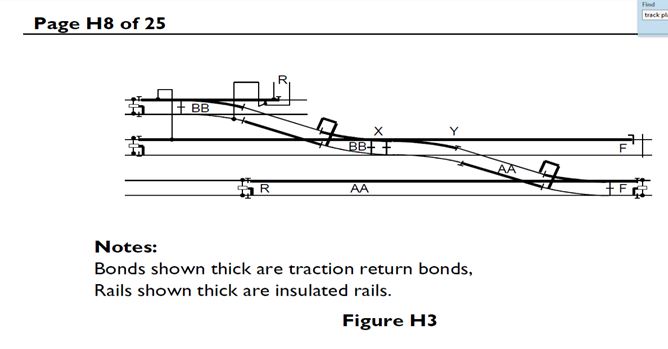
Traction return bonding essential to the operation of track circuits must be shown on all bonding plans (see Figure H3).
Railway Bonding Details in D.C. Electrified Areas
Minimum length of track section (Railway Bonding Details in DC Electrified Areas)
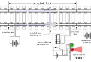
The minimum length of a track section shall be greater than the harmonized maximum spacing between adjacent axles of vehicles, as set out in section 3.1.2.1 of ERA/ERTMS/033281 unless alternative safeguards are provided to prevent the track section from showing clear when a vehicle is standing over it.
ERA/ERTMS/033281 sets out the harmonized maximum spacing between adjacent axles of vehicles of 20 m.
Where the work involves track replacement only, the minimum length of a track section of 18.3 m could be retained for work that does not include a change to the train detection system’s capability.
Where the minimum length cannot be achieved, alternative safeguards (for example, sequential proving of the adjacent track section) are provided to prevent the track section from being falsely detected as clear.
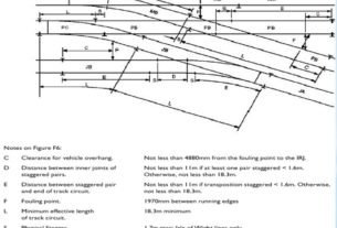
Examples of a minimum length of track section are shown in Fig below
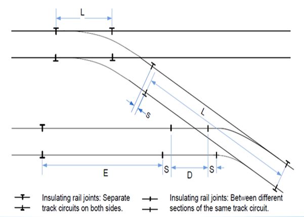
Dimensions Value
D = Distance between inner joints of staggered pairs Not less than 11 m if both pairs staggered < 1.6 m. Otherwise, not less than 20 m
E = The shortest distance between a staggering pair of IRJs and the boundary of a track section ……….. 20 m minimum
L = Effective length of track circuit 20 m minimum
S = Physical stagger…. 2.1 m max: Signal rail overlap on electrified lines and 2.6 m max: Other cases