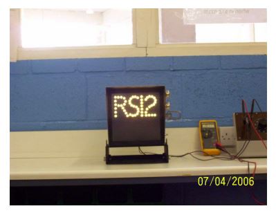
Prototype RS Indicator|Point Selection Schematic|Four Foot Points Machine
•Route secure indicators are mounted at the side of the track and use LEDs to display a route indication to the train operator.
•They are not used in normal operations.
•They are used after a failure:
to permit failed trains that cannot communicate with the VCC to move over points.
to permit communicating trains to move over points if a flank point detection has failed.
to permit trains to move over points if the VCC or loop has failed.
•In addition to seeing the route indicated on the RSI indicator, the train operator must have authority from the control operator over the radio or telephone before moving the train.
A Route Secure (RS) indicator is commanded to be lit or not lit by the SCS, after the required route has been set up.
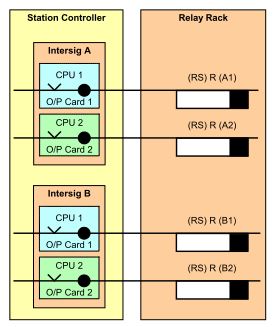
* Slow-to-drop output relays keep the RS illuminated if the SCS changes over from INTERSIG A to INTERSIG B.
* Because the SCS only commands ‘lit’ or ‘not lit’, the relay rack is required to select the RS aspect based on the detected position of the points in the route.
* Once the SCS commands the RS to light, if the initial conditions (i.e. point detection) are lost the SCS does not switch off the RS. The relay rack has to do it.
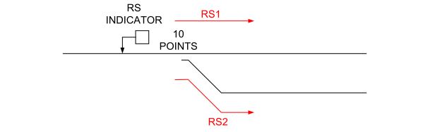
RS Lighting Circuit Schematic
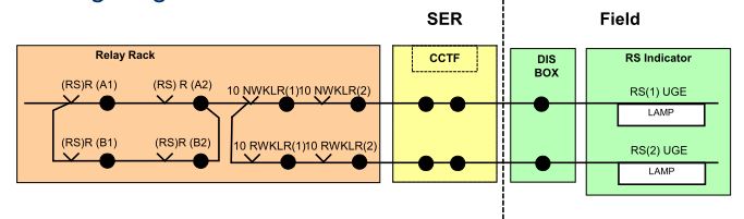
The SCS (either INTERSIG A or B) commands the RS to be lit, and the relay rack selects the aspect (based on 10 points normal or reverse, in this example).
Where an RS route goes across an SCS boundary, an interface circuit is necessary, even if both SCSs are in the same SER.
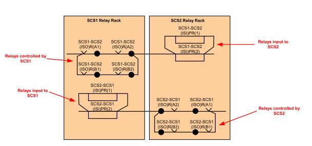
The two SCSs output ‘slot’ indications to each other, indicating that the track is safe for the RS move to enter the territory controlled by it.
* The ISI PR relays are only used as inputs to the SCS
* The ISI PR relays are not used in the RS indicator lighting circuits
Prototype RS Indicator
POINT CONTROL
* SELTRAC controlled points require a total of 3 SCS outputs to control them: Point Command Normal (PCN), Point Command Reverse (PCR) and Point Command Move (PCM).
* To move the points normal requires PCM and PCN outputs on.
* To move the points reverse requires PCM and PCR outputs on.
* PCM outputs can only be allocated to output card 3 (outputs 1-6 only).
* PCR outputs can only be allocated to output card 2 (outputs 1-6 only).
* PCN outputs can only be allocated to output card 5 (outputs 1-6 only).
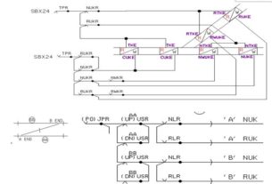
Point Selection Schematic

•Points to note:
* Outputs from both CPU 1 and 2 required to move the points.
* If the SCS point move outputs have been switched on for 7 seconds and the point detection is not obtained, the SCS switches off its outputs and raises an alarm.
* Points cannot be moved if tracklocking axle counter block is occupied.
* Deadlocking bypass (DLXR) relays can bypass QR contacts if axle counter fails.
* No diversity in NLR/RLR or NWR/RWR functions (i.e. single relays used).
* NLR/RLR contacts are used to operate ground lock.
* Slow to pick NWR/RWR are used to operate the point valve (this gives the ground lock time to disengage before the points try to move).
FOUR FOOT POINT MACHINE
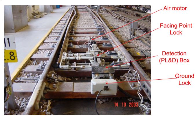
4 Foot Points Movement Clip
Point control schematic
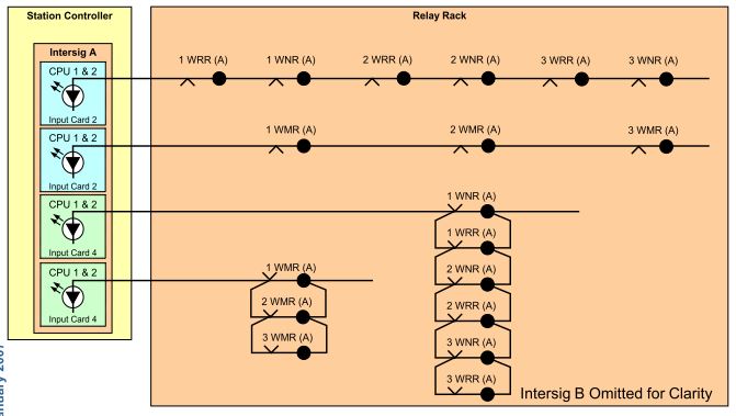
POINT CHECKBACKS
* Point checkback circuits are different from those for RS or other outputs.
* The point movement (WMR) and point direction (WRR/WNR) output relays are checked back separately.
* The four point checkback inputs check ALL point relays controlled by the SCS in each input (summary checkback).
* The four checkback inputs are anti-valent (two normally energised, two normally energised).
* When a point move command is given, the on/off state of all four inputs should be reversed.
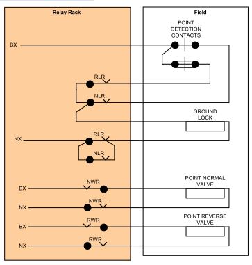
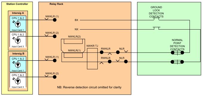
POINT DETECTION
* The external point detection circuits are powered at 110V AC with QXR1 transformer rectifiers.
* Two relays are used for normal and two for reverse detection.
* The machine detection contacts must be double cut.
* The detection inputs to the SCS prove correspondence between the detection and the control relay (NLR/RLR).
* Each end is detected separately and input separately to the SCS.
* Detection inputs can only be allocated to input cards 1 and 3.
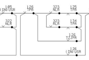
• Example: Single ended 4-foot point – normal detection schematic
Rail Gap Indicators (RGIs)
•Rail Gap Indicators (RGIs) light up if the traction power on the track ahead is switched off.
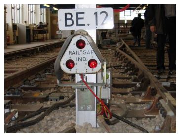
•RGIs have three lamps (six on JLE).
•RGIs are not part of the vital signalling system.
* The traction power is monitored by ‘Current On Line’ relays
* We use repeat relays (COLPRs) on the relay rack to control the RGIs
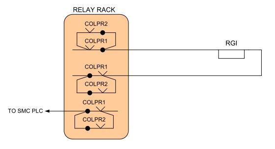
* We also tell the SMC the state of each traction section through SMC PLC inputs generated from COLPRs
* When the traction power is off, the COLPR is energised
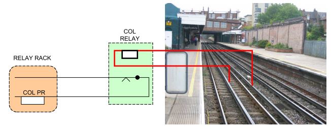
* As well as the COL relay, the rail gap indicator is controlled by the points detection
* Only facing points detection is used
* Only routes which are possible in the signalling system are considered

•What would be the controls for this RGI?
•Diverse COLPR relays (and concentric cable) are used even though the circuits are non-vital
•The contacts are used in parallel to maximise the possibility of lighting the RGI and notifying the SMC if one relay fails to pick when the traction power goes off.
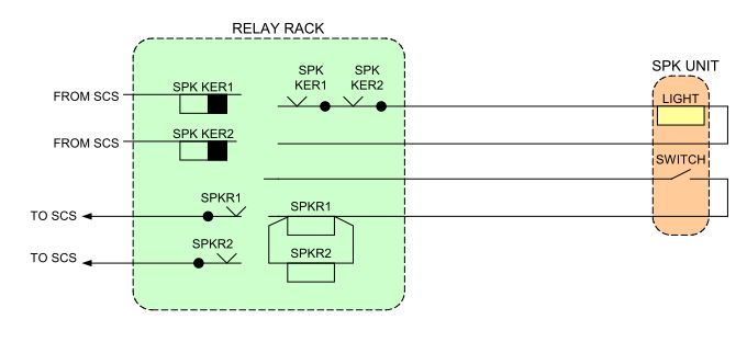
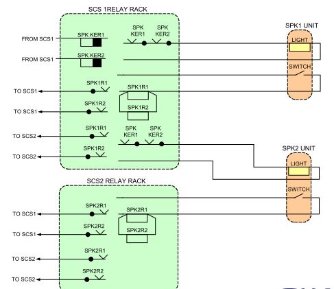
Staff Protection Keyswitch
•SPKs are used by maintenance staff.
•When the SPK is operated, it protects a section of the track so that no trains can enter it and no points can be moved.
•The SPK is monitored by the relay rack which passes the status to the SCS.
•If the SCS/VCC detects an SPK is operated, a light is switched on at the SPK to show the maintenance staff that the area of track is .protected.
•When the keyswitch is operated, the key is removed from the switch.
•When the key is put back into the switch, the protection can be released by turning the keyswitch back to the normal position.
* Sometimes the area protected by the SPK is controlled by more than one SCS.
* Note that only one SCS controls the light (the ‘Master’ SCS).
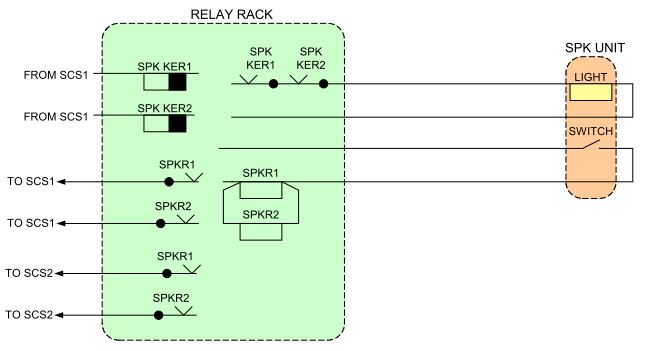
* Sometimes there are two SPKs that protect the same area.
Useful Documents
Relay Rack Hardware Requirements Specification – 3CU 00550 0210 DTZZA
INTERSIG Parallel Input/Output Interfaces – 3CU 00550 0198 PBZZA
Station & Trackside Interface Specification – 3CU 00550 0156 PBZZA