Network Rail Lineside Location Design
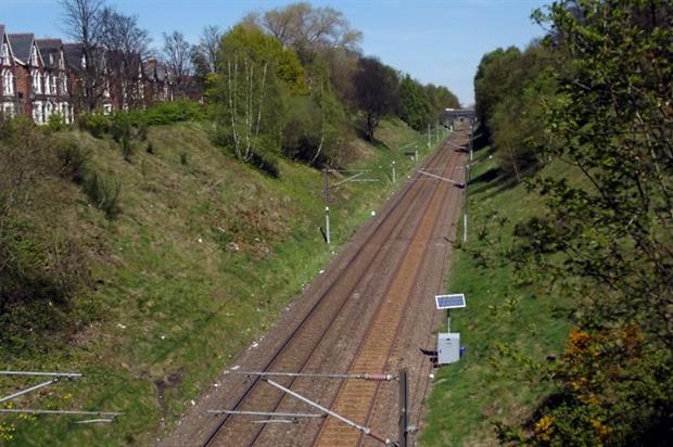
Controls to various functions are distributed from the Signal control box to the site through intermediate Location boxes / REBs. The position of Location box is decided by the functions/equipments to be covered and the size and number of cases is decided by considering the quantity, and type of equipment to be accommodated.
The Location Area plan derived from the Scheme plan shall show the details of the mileage, boundary, and any other relevant information like TFMs. (Ref page N38) Details of all the cases of a single Location should be in a single set of drawings. All disconnection boxes should be shown on circuit diagrams.
Design details
Index sheet
Besides the details of all the design sheets indicating the version nos, the Index sheet should provide an extract of the Location area plan showing the position of all trackside functions controlled from that location.
Index sheets should be numbered in the same series as the drawings to which they apply. Index sheet(s) shall consequently be listed first on the index. AIR is not o be indexed.
Case Layout
Views of the apparatus case from the front and rear should be shown with profiles of all equipment, fuses, and terminals drawn proportionately. For equipment rooms and buildings(REB) an equipment room layout is also to be provided.
Power supplies and Busbar layout
This part of the drawing should show all the details of the power supply arrangements including supply point, switching and isolation points, transformers and TJs with ratings, etc and also local batteries with charger arrangements, power supply fuse and terminal analysis with circuit names and supply looping. Where supplies are available from more than one power supply point, each should have distinct identity.
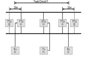
Train Detection Circuits
This should cover the details of Track circuits, Axle Counters and Treadles:
1. Outgoing track circuit repeater circuits
2. Track circuit equipment wiring
3. Rail connections and tail cables
4. Disconnection box and/or impedance bond internal wiring
5. Treadle or Axle counter circuits
Track circuit connections shall be in detail. With dis – box or impedance bond terminals, rail connection points, IRJ positions, line name and up/down directions.
Signal Circuits
Should show:
1. Incoming signal control circuits, with trough circuits back to its origin, unless originating from an interlocking.
2. Outgoing signal repeater circuits
3. Signal lighting circuits and tail cables
5. AWS circuits
6. First filament failure circuits
Point Circuits
1. Incoming point control circuits
2. Outgoing point detection circuits
3. Point detection feed and track side circuits and tail cables (separate cables for i/c & o/g detection)
4. Supplementary detection circuits showing the orientation of detector on an extract of the layout.
5. Point machine/clamp lock internal wiring
Miscellaneous circuits
1. Apparatus case heater wiring with fuse
2. Lighting with fuse and switch, where documented in design spec
3. Telephone plug point, where specified
4. Ground frame circuits
5. Level crossing circuits
6. Other circuits as per requirements
Network Rail Lineside Location Design, Design details, Case Layout, Power supplies and Busbar layout, Train Detection Circuits, Signal Circuits , Point Circuits , Miscellaneous circuits ,

https://waterfallmagazine.com
You can definitely see your enthusiasm within the work you write.
The world hopes for even more passionate writers like you who aren’t afraid to mention how they believe.
All the time go after your heart.