Microstation
What is Microsation?
Microstation is a software like AutoCAD and other draughting software that using for Computer aided designing. Almost all commands in microstation is similar to AutoCAD for 2D drawings, but for 3D designing, Microstation have it’s own additional module like Modular.
Advantages of Microstation from AutoCAD
- Microstation required only of 5MB free space.
- This is a duel window/monitor based application.
- Reentering of command is not required
- Editing attributes in the cell (blocks in AutoCAD) is possible.
- Multiple views (upto 8) of the drawing is simplifying the view structure.
- Creating Macro application is very user friendly.
- Editing datafields (Special type of text) is more useful for standardisation of text properties.
- Always getting information about active commands from status bar.
Working with Design Files
A MicroStation document file is called a design file. MicroStation’s File menu has items for creating, opening, and saving design files. These file management operations and others can also be performed using the MicroStation Manager dialog box

You cannot have more than one design file open or active in MicroStation at a time. If you open a design file when one is already active, MicroStation automatically closes the first file. However, you can view the contents of other design files by attaching them for reference to the active design.
When you create a design file, MicroStation copies one of the provided templates or seed design files. The seed file is copied to a new file name that you specify in the Create Design File dialog box.
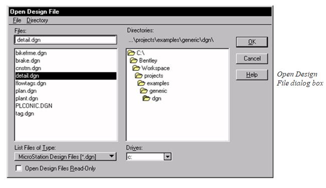
To open a design file as the active design file
From the File menu, choose Open.
The Open Design File dialog box opens.
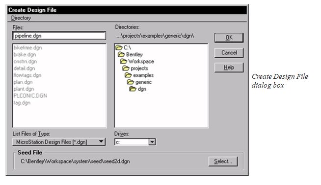
To create a design file and open it as the active design file
From the File menu, choose New.
The Create Design File dialog box opens.
The default filter is “*.dgn.”
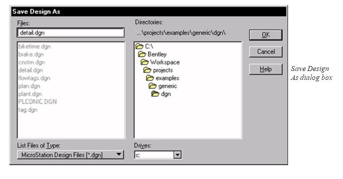
To “save as”
From the File menu, choose Save As.
The Save Design As dialog box opens.
Using MicroStation Manager
When you start MicroStation without designating a design file to be opened automatically, the first dialog box you see is MicroStation Manager.
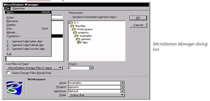
MicroStation Manager can be used to perform a variety of useful file management functions including backing up, copying, deleting, compressing, merging, renaming, and opening design files, as well as creating new directories and backing up entire directories. These functions are performed by choosing items in MicroStation Manager’s File and Directory menus, which have features beyond those in other dialog boxes
Exiting MicroStation
As you work, MicroStation saves all changes you make to the active design file to disk (assuming you have not turned off the default “Immediately Save Design Changes” toggle under Workspace>Preferences>Operations). After you close the design file, you can no longer undo changes with MicroStation’s Undo feature. Therefore, be sure to undo any unwanted changes to the design file before you exit MicroStation.
To exit MicroStation
From the File menu, choose Exit.
or
From the application window menu (if one exists), choose Close.
or
In the MicroStation Manager dialog box, click Cancel.
Using Drawing Tools
MicroStation has dozens of drawing tools (called tools, for short). They are organized for convenient selection in tool boxes. A tool box that is open on the screen in its own window is said to be floating. You can change the arrangement of tools in a floating tool box by resizing its window.
Tools are represented in tool boxes by icons. For simplicity, the term “tool” is used to refer both to a tool and its icon.
The Main tool frame opens automatically the first time you start MicroStation along with the Primary tool box and the Standard tool box. The Main tool frame is docked by default to the left edge of the MicroStation window, and the Primary and Standard tool boxes are docked by default to the top edge.

MicroStation has dozens of drawing tools (called tools, for short). They are organized for convenient selection in tool boxes. A tool box that is open on the screen in its own window is said to be floating. You can change the arrangement of tools in a floating tool box by resizing its window.

To open a child tool box of the Main tool frame
In the Main tool frame, press on the tool that is the “representative” from the child (and hold the Data button down)..
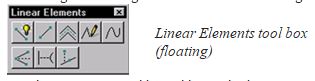
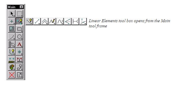
For example, to open the Linear Elements tool box, press on the second tool in the right-hand column in the Main tool frame (Place SmartLine in the default tool box configuration). As long as you hold down the Data button, the Linear Elements tool box remains open. You can drag across the tool box to select a tool. When you release the Data button, the tool box closes and the selected tool displays in the Main tool frame.
In the Main tool frame, press on the tool from the desired child, and drag the child off the Main tool box. You have to drag the pointer a certain distance from the Main tool box before it is “torn off.” When the pointer is far enough away, the tool box’s outline displays dynamically. or Use the Tools menu or Use the Tool Boxes dialog box.

For example, to open and float the Linear Elements tool box using the first method, press on the second tool in the right-hand column of the Main tool frame and drag the Linear Elements tool box off of the Main tool frame.
Working with the selected tool
MicroStation has several aids to help you use tools. Settings that affect how a tool works can be controlled in the tool settings window. The Status Bar along the bottom border of the MicroStation window displays prompts and messages about the selected tool.
Tool settings
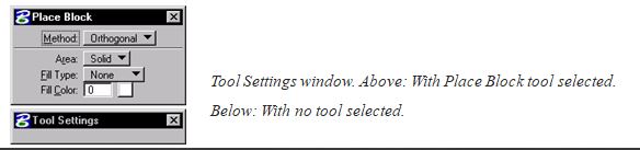
Tool settings affect the operation of a specific tool. For example, the Method setting sets how a rectangle is drawn with the Place Block tool. In a tool box that is attached to its parent (not floating), tools with associated settings display a triangle.
Rather than forcing you to adjust a tool’s settings each time you select that tool, tool settings remain in effect until you change them. This makes MicroStation more efficient to use, but also means you must keep the active tool’s settings in mind or displayed on the screen.
Tool Settings window
The tool settings window is used to adjust tool settings. For example, if the Place Block tool is selected, controls for adjusting the tool settings Method, Area, Fill Type, and Fill Color are displayed in the window, and the window’s title bar reads “Place Block.” If closed, the window opens automatically when a tool with settings is selected.
Checking the status bar
It is recommended that you make it a habit to frequently check the status bar at the bottom of the application window (or the screen).
It displays a variety of useful information, including prompts, messages, and the name of the selected tool. If you are not sure “where you are” with a tool, look in the status bar.
The status bar is divided into two sections:
Left-hand section of status bar
The left-hand section ordinarily shows the name of the selected tool (or view control) followed by either a greater-than sign symbol (>) or a colon (:) and message text.
- Message text that follows a “>” is the selected tool’s prompt; a tool’s prompts guide you step by step as you the perform an operation with a tool.
- Message text that follows a “:” is a message that indicates a possible problem.
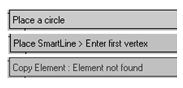
As you move the pointer on tools in a tool box, the name of the selected tool and the associated message text are replaced with a description of the tool over which the pointer is located. This is intended as a form of on-line assistance.
Right-hand section of status bar
The right-hand section ordinarily consists of a series of fields. From left to right, the status information indicated in these fields is as follows:
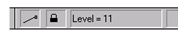
- Snap Mode setting. In MicroStation, Snap Mode cannot be changed.
- The Locks icon does not indicate status information. Clicking it provides an alternate means of access to the Settings menu’s Locks sub-menu.
- Active Level setting.
- The count of selected elements . If this field is blank, no elements are selected.
- Whether the fence is placed . If this field is blank, the fence is not placed.
- Whether changes to the active design file are unsaved. If the field is blank, there are no unsaved changes. If the field has a red icon with an “X” through it, the active design file is open for “read-only” access.
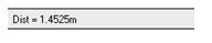
When you enter a tentative point or request quantitative information — for example, distances or angles using tools in the Measure tool box — the fields in this section to the right of the Snap Mode field are temporarily replaced with a single message field.
To restore the fields to the right-hand section
Press the Reset button. (To find the location of the Reset button on your system’s graphic input device, see Using the Mouse or Digitizing Tablet.) Click the status bar.
Preparing to Draw
Except for user preferences, there are no default settings in MicroStation . The settings described in the following sub-sections can be saved in the design file on disk. To preserve changes to these design file settings between sessions, you must explicitly save the settings.
Seed files
When you create a design file, you identify a seed file as a template for the design file. The new design file is actually a copy of the seed file.
Seed files do not (necessarily) contain elements, but, like other design files, they do contain settings and view configurations. Having a seed file with customized settings keeps you from having to adjust settings each time you create a design file. If you wish, you can have a different seed file for each type of drawing you do.
To select a seed file
1.From the File menu, choose New.
The Create Design File dialog box opens.
2.In the Seed File section, click the Select button.
The Select Seed File dialog box opens. The default filter is “*.dgn.“
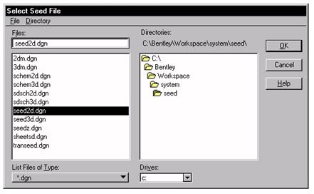
3.(Optional) To list all files in the Files list box, choose All Files from the List Files of Type option menu.
4.(Optional) To select a different source disk drive, choose the desired drive from the Drives option menu.
5.(Optional) To select a different source directory, use the Directories list box.
6.In the Files list box, select the desired seed file.
or
In the Files field, key in the name of the desired seed file.
7.Click OK.
Using View Controls
View controls are used to manipulate a view, the portion of the design displayed in a view window. The most commonly used view controls can be selected in the View Control Bar on the bottom border of each view window
![]()
Some of the most useful view controls include the following:

The Update View view control is provided to redraw the display when an operation leaves a view with an incomplete display. For example, if you delete an element that crosses in front of (and partially obscures) another element, the part of the underlying element that should be revealed might not be redrawn automatically.

Window Area, which is used to designate a smaller area to display in another view to see details.

Fit View, which is used to fit the entire design in a view (for the “big picture” or to get your bearings).

Rotate View, which is used to rotate a view.

View Previous, which is used like an Undo function to negate previous viewing operations, as many as eight per view.
Tool Bars
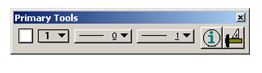
Primary Tool Bar
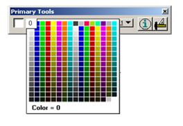
Colour: This Displays the active colour
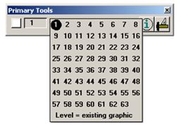
Level : This displays the active level
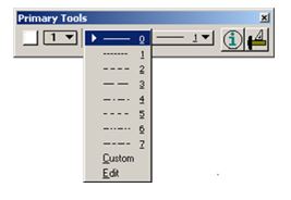
Line Style: This displays the active Line style

Line Weight: This Displays the active Line Weight
Tool Bars

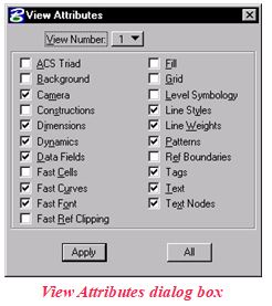
Setting View Attributes
Views have a number of attributes that you can adjust individually for each view window.
- Some view attribute settings determine whether parts of a design — elements on particular levels, text, fill, and drawing aids such as the grid — are displayed.
- Others determine the manner in which the design is displayed — with or without a background image or dynamic updating, for example.
Level display
Each element in the design is on one of 63 drawing levels. Levels are analogous to transparent overlays: In different combinations they make it easier to see parts of a design; together, they show the entire design. The Active Level is the level on which elements are placed.

Levels can be named and grouped hierarchically. For example, levels named “chairs,” “tables” and “desks” could be grouped together as “furniture” and turned on or off as a group. In turn, “furniture” could be a part of a higher level group of levels.
Other view attributes
View attributes other than level display are set in the View Attributes dialog box. Some determine whether parts of a design and drawing aids will be displayed. Others determine how the design file is displayed.
To turn other view attributes on or off
1.From the Settings menu, choose View Attributes (or press < ctrl-B >). or From any view window’s control menu, choose View Attributes.
The View Attributes dialog box opens.
2.From the View Number option menu, choose the number of the view whose attributes you want to change.
3.Turn the desired view attributes on or off by clicking the check boxes to the left of the appropriate items.
4.Click the Apply button.
Tool Bars, Setting View Attributes, Level display, Other view attributes, To turn other view attributes on or off