Metro PIDS PAS Training
Introduction
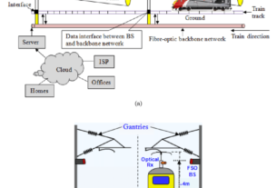
1. Public Information Display System (PIDS)
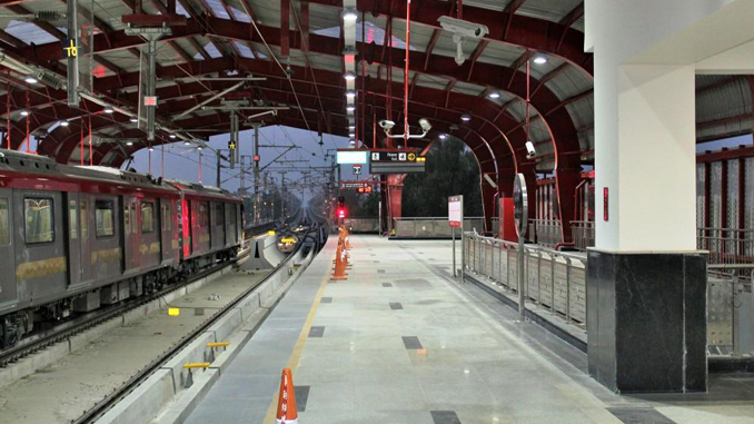
2. The purpose of PIDS is to display at station concourses and platforms on-line information about scheduled train arrivals and departures and other general purpose messages (normal and emergency) such as smoking is prohibited, evacuation messages etc.
3. It displays information in any combination of English text, Hindi text, numerals, animated graphics, punctuation and symbols in real-time.
Operational Control Center
OCC Theatre
FOTS
Stations
SCR SCR SCR
Display Boards Display Boards Display Boards
Display Boards Display Boards Display Boards
Display Boards Display Boards Display Boards
Display Boards Display Boards Display Boards
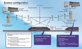
PIDS/PAS functional blocks
It consists of the following functional blocks:
The Operational Control Centre (OCC).
1. The OCC is the global control centre for the PIDS/PAS system.
2. From the OCC system wide control of SCRs is possible.
The Station Control Rooms (SCR).
1. The SCR is the local PIDS/PAS installation exists in each station.
2. It manages the local PIDS/PAS system of that station.
Operational Control Centre
FOTS
Master OCC LAN PIDS/PAS
Clock Server
AT S Central PIDS/PAS
Server MMI
SCADA PIDS
Server Backup
PAS
Backup
Operational Control Center Configuration
PIDS/PAS Server
1. The central server is located in the OCC. This server, with the necessary back-up and redundancy modules is connected, via the central router to the central ATS server, to the Local ATS servers, to the SCADA server, and to the Master Clock unit. The PIDS central server is common to the PAS central server.
2. The central server is composed of two machines configured as a Windows NT cluster, with shared disk storage. When one machine fails, the services are automatically started on the backup machine, which reads the state information from the shared disk array.
3. The central server and the station servers are synchronized via the clock distribution system.
Master Clock
The Master clock provides for the system wide time synchronization.
ATS Central Server
The ATS server sends information on train arrivals and departures to PIDS local ATS servers.
SCADA Server
The SCADA server receives and manages alarms generated by PIDS/PAS.
PIDS/PAS functional blocks
PIDS/PAS Servers
The two servers at a single station are symmetric: one is active, and the other is on hot stand-by. Both systems receive all the external events and update the local state, but only the active system sends output to the displays or loudspeakers. Both systems are constantly monitoring each other for a failure. When one system fails the other automatically takes on the active role. When the changeover occurs an alarm indication (alarm pop-up window and audio signal) is shown on the active MMI.
Submaster Clock
The Submaster Clock provides a local backup for the system clock in case the latter is unserviceable .
ATS Local Server (LATS)
The local ATS server receives and manages ATS data from the central ATS server.
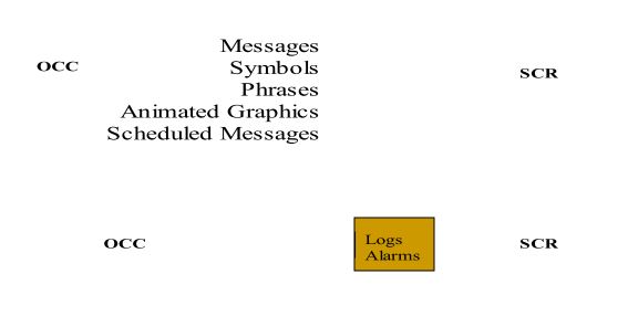
The Main Window of PIDS/PAS Application
The main window is divided into different areas by function. Selection area Current Station area Alarm area
The Display Boards Tree (3)
This panel allows us to select or deselect display boards, in order to, send a message.
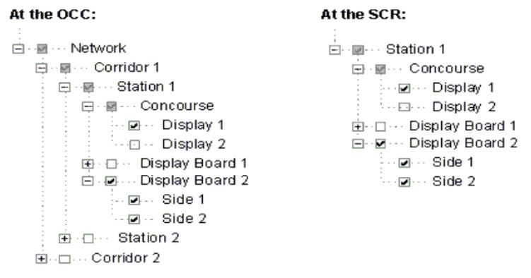
The Display Boards Tree (4)

The Alarms Panel (7)
The Alarm Panel displays alarms for:
Equipment alarms.
Display boards.
Public Address Zones.
Communication with other systems.
1. Internal PIDS alarms (i.e. disk full).
2. Operational alarms (i.e. message priority conflict).
OCC/SCR Synchronization
Public Address System(PAS)
PAS provides broadcasting of voice messages to passengers / staff in all stations, depots and OCC. It can also be used for emergency evacuation broadcast in case of emergencies.
1. The PAS announcements are co-ordinated automatically with PIDS for Real Time Passenger Audio Broadcast.
2. PAS support :
3. Messages announcements in HINDI and English or any combination of these languages.
4. Different Live or Recorded announcements to separate Zones or Group of Zones simultaneously within a station.
5. Announcements from Designated Hand Portable Radios to a set of pre-defined Zones at each station.
Four Major Types of Messages
Fixed Message
-Smoking is prohibited in the entire station.
Pre-formatted with data to be added.
1. This station is…………
2. Due to ……..failure, the arrival of the trains shall be
delayed.
Instantly recorded messages.
Live audio broadcast.
1. According to situation, such as for crowd management
in case of accident.
Message Priority
1. Instantly created / pre-formatted message relating to emergency like fire etc from the SCR.
2. Instantly created / pre-formatted
message relating to emergency like fire etc from the OCC.
3. Train arrival / departure related messages triggered automatically by the TC&S system.
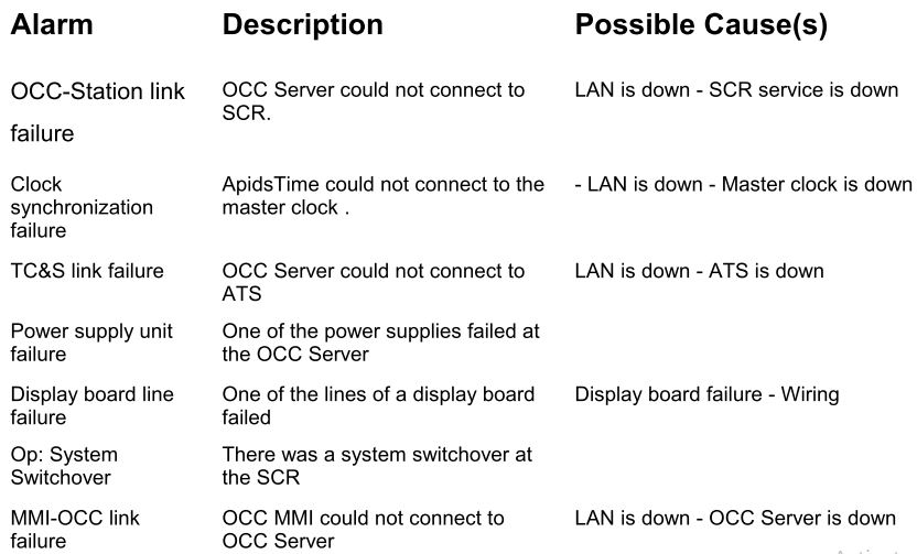
Alarms (Major & Minor)
1. Loss of the entire PIDS facilities at a location.
2. Loss of clock synchronization.
3. Power supply unit failure.
4. Loss of one side of a display board.
5. Message priority conflict.
6. Failure of communication link between OCC and station
PIDS.
7. Loss of both sides of a display board.
PIDS alarms and their possible causes.
Components of PAS
Codec
Telcommander
Amplifiers
Gate Keeper
Zone-8 M
Noise Level Controller (NLC)
Loudspeakers
Codec
Codec is a device that encode and decode the information from digital to analogue signals. It does this by using two Xchanger cards (one is master, located in the OCC server and other is slave, located at each station client server).
Telcommander
Its main task is to interface the Radio System via the PABX, allowing the portable Radio units to address the PAS.
Amplifiers
Signal sources like microphones, CD players, cassette DAT and MiniDisc recorders, do not have the capacity to produce enough energy to directly feed a loudspeaker. It is therefore necessary to use an amplifier that transforms the low power signals of the signal sources in signals with sufficient power to feed the system loudspeakers.The numbers of amplifiers are variable according with the number of physical zones used in each station. The standard procedure is to install one amplifier by zone, and n loudspeakers per zone
Gate Keeper
This equipment is used as an amplifier and loudspeaker controller that performs the
following tasks:
1. Detect and replace any malfunctioning amplifier.
2. Inform the status of each amplifier and possible cause of failure.
3. Distribute the audio signal directly to the loudspeakers.
Zone 8 Selector
1. Dispatch messages to the required zones, respecting the priority scheme between terminals.
Noise Level Controller (NLC)
The human and traffic conditions affect the levels of background noise. Therefore, in order to deal with this issue carefully, the
system will adjust the volume of the announcements to a higher level than the background noise, by using the NLC and NLC sensors.