Centralized Traffic Control
1. Traffic control system (TCS) or centralized traffic control (CTC) is a block system under which train movements are authorized by block signals whose indications supersede the superiority of trains for both opposing and following movements on the same track. FRA 236.828
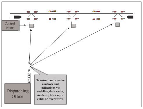
2. Signal control – train movements are controlled by signal indication, usually by a dispatcher at a remote location via codeline, modem, or data radio.
Definitions
Control – A request sent from the dispatch office for an operation of a device at a control point.
1. A request for a switch to throw or a signal to clear.
2. This is either a direct request from the dispatcher or an automated request from the control computer. (A stored route)
Indication – The information sent from the control point conveying the events that occur at that control point.
1. A signal clearing or track circuit becoming occupied.
2. This is initiated by any change of a condition monitored at the control point.
Vital circuits – circuit that directly affects the safety of train operation. (For example, a signal or switch control circuit)
1. Controls are routed through vital relays, which check the integrity of the signal system, before allowing a signal to clear or a switch to throw.
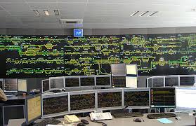
Non-vital circuit – A circuit whose failure would not cause an unsafe condition to exist. (For example, a control or indication circuit) Indications are used as a graphical representation in the dispatch office, to allow the dispatcher to “see” what is occurring in the field.
In CTC territory, trains are governed by signal indication.
1. The dispatcher controls trains by determining which signals to send a request to clear.
2. Signals are interconnected so that no two signals will be allowed to clear into the same block between control points in opposite directions.

Sequence of Events of Events
1. Dispatcher requests an operation of a component at a control point.
2. Control is sent via the necessary communications device.
3. Control is received at control point.
4. Vital circuits are checked and, if safe, the operation is completed.
5. Control point sends indication to dispatcher.
6. Indication is displayed on the dispatcher console.
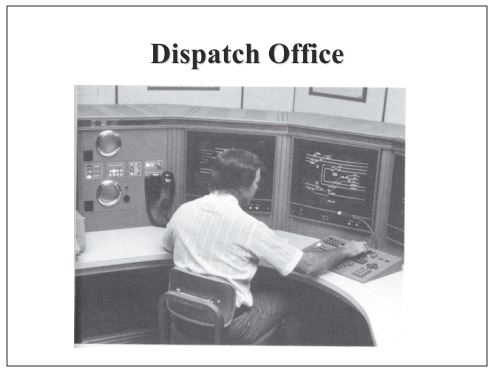
Dispatch Office
1. Dispatch offices have evolved from toggle switches, push buttons and light bulbs to computer workstations with “point and click” interfaces and graphical displays.
2. Dispatchers select a device to control and the computer determines the means to send that request to the field
control point.
3. The control is then sent via modem, microwave, data radio or any combination of communication devices.
4. Indications are received from the field control point, interpreted, and displayed as an image for the dispatcher.
In the dispatch office are a variety of troubleshooting tools available to the signal department employees.
1. Data recording of dispatcher requests and keyboard commands.
2. Data recording of controls and indications from the “codeline”.
3. Monitoring capabilities for on-site personnel.
“Office logic” may be used to prevent unsafe controls from being sent from the dispatch office.
1. For example, if an eastbound signal is requested the computer would not allow a request for a switch to throw in that route.
2. This is not a fail-safe system.
3. This is not used to replace the vital logic of the field control points.
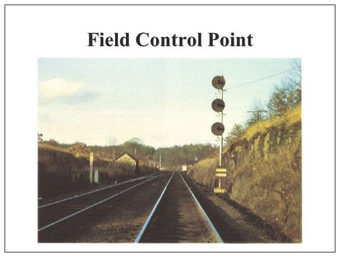
Field Control Point
1. The control point receives the control from the dispatcher.
2. Vital circuits are checked for conflicting signals, signals “in time”, switches in correspondence, etc.
3. If it is safe to operate device requested, the operation occurs – switch throws, signal clears, etc.
4. When operation is completed, the control point sends an indication to the dispatch office, updating the office of the current conditions at the control point.
In addition to the vital controls available to the dispatcher are useful tools for the signal personnel.
1. Remote control of switch heaters. (Snow melters)
2. Remote indication of power failure.
3. Remote indication of fire or break-in.
4. Dispatcher availability of a maintainer call.
Signals at control points are absolute signals
1. Signals normally display a stop indication until requested by the dispatcher or control operator.
2. An automatic block system (ABS) is used between control points.
3. Block occupancy indications are sent to the dispatcher or control operator from the adjacent control points.
4. Hand-throw switches in a control point or in the block between control points must be protected with an electric lock or an exiting signal.
Centralized Traffic Control Summary
1. CTC allows for a safe, efficient, and cost effective means of controlling trains.
2. CTC increases track capacity and train speed by expediting train movement by lining routes and clearing signals prior to a train’s arrival at a control point.
3. CTC allows a single dispatcher or control operator to manage a large section of track, interconnected signals and control points.
4. CTC allows a redundant safety system to prevent unsafe requests from being sent to the field control point.
Introduction to Centralized Traffic Control, Signal control, Control, Indication, Vital circuits, Non-vital circuit,Sequence of Events of Events, Dispatch Office,Field Control Point,Signals at control points are absolute signals
Is there any post graduation course for railway signalling ??