
Interface Design Railway
Hardware
Microlok II Equipment consists of:
1. Card file
2. CPU PCB
3. Power Supply PCB
4. Vital Output PCB
5. Vital Input PCB
6. Non-vital Input/Output PCB
7. VCOR – Vital Cut Off Relay
8. Wiring hardware
Card File
Each card file consists of:
- 20 Slots to accommodate various PCBs that are used in a system.
- Slot nos. 1 to 15 and 20 are used to accommodate Non-vital or Vital I/O PCBs.
- Slot no. 16 & 17 are used to accommodate Power supply PCB.
- Slog no. 18 & 19 are used to accommodate CPU PCB.
- A mother board connecting all the 20 Slots.
- Suitable to mount on a 19” rack.
CPU PCB
- Each card file to have one CPU PCB and always placed in slot no. 18 & 19.
- Processor used is Motorola 68332.
- Processor speed is 21 Mhz.
- 4 flash EPROMs of 8 MB to store executive and application software.
- Two fast Static RAM (each 64KB) to process vital data.
- Four Static RAM (each 64KB) to store events and errors.
It has Five serial ports to communicate with peripheral devices.
- Port 1 & 2 are RS 485 type for Vital control systems such as MLKII.
- Port 3 is RS 432 type for other Non-vital control systems.
- Port 4 is RS 232 type for other Non-vital control systems.
- Port 5 is used exclusively for Diagnostic purpose.
Functions of CPU
- Continuous monitoring of Vital Board status
- Monitoring system internal operation for faults and responds to detected faults
- Process application logic based on inputs received and deliver outputs to drive external gears
- Recording system faults and routine events in user-accessible memory
- Monitoring and controlling serial communication ports
- Controlling power to vital outputs through external VCOR relay
Power Supply PCB
Each card file to have one Power Supply PCB and always placed in slot no. 16 & 17. Function:
1. Power supply PCB is basically a DC-DC converter that converts 12V DC input supply in to +12V, -12V and +5V required for various board functioning.
2. Based on diagnostic check by CPU, PS PCB receives 250 Hz signal from CPU and extends supply to VCOR relay.
3. Provides isolated supply to internal circuit.
System Operating Power

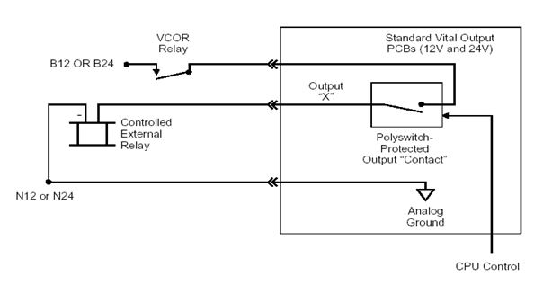
Vital Output PCB
- Each Vital Output PCB has 16 Outputs.
- Suitable for 12V and 24V DC application.
- Each Vital Output can drive an output device such as any Q-Series relay. This output relay in turn controls signals, points, crank handle, siding control, level crossing etc.
- Since Vital Output drives the relay which controls important out door gears, all the Vital Output boards are continuously diagnosed by a CPU. Any abnormality in any of the outputs will shut down the system to ensure safety.
- The status of Vital Output is known from LEDs available in front of the PCB.
- Each Vital Input PCB has 16 Inputs.
- Suitable for 12V and 24V DC application.
- Each Vital Input is assigned to read the status of out door gears such as Track circuits, Point detections, Crank handles, Siding controls, level crossing etc.
- Since the Vital Inputs read the status of out door gears, they are normally configured with double cutting arrangement using relay contacts.
- The status of Vital Input is known from LEDs available in front of the PCB.
Non-vital Input/output PCB
- Each Non-vital I/O PCB has 32 inputs and 32 outputs in one PCB.
- Suitable for 12V or 24V DC application.
- Non-vital inputs are Panel push buttons and keys.
- Non-vital outputs are Panel indication LEDs, counters and buzzers.
- The status of Non-vital Input/Output is known from LEDs available in front of the PCB.
Vital Cut Off Relay – VCOR
- Each Card file will have one VCOR to ensure the healthiness of the system.
- VCOR has 6 F/B dependent contacts each rated for 3 Amps.
- When system is healthy, the coil receives voltage from PS PCB which in turn controlled by CPU.
- Power to Vital Output board is controlled by VCOR, thus ensuring safety.
Wiring Hardware
- 48 Pin Address select PCB and Connector assembly for Vital Input and Vital Output cards.
- 96 Pin Address select PCB and Connector assembly for Non-Vital I/O cards.
- 48 Pin Connector Assembly for PS and CPU PCB.
- EEPROM PCB to configure various serial communication ports.
- Keying plugs to ensure coding of each type of cards.
Address Select PCB
- Used to address particular slot of the card file.
- Each address select PCB consists of 6 nos. of Jumpers.
- These jumper settings are unique and shall match with the definition of cards in application program.
- 48 Pin address select PCB is used for Vital Input and Output boards.
- 96 Pin address select PCB is used for Non-vital I/O boards.
Connector Assembly
- Each connector assembly consists of connector receptacle (i.e cover), guide pair to fix the connector on the card file & crimp contacts.
- Connector Assemblies are used to connect MLKII cards with Relays, relay contacts and panel with help of pre-wired cables.
- The 48 Pin connector assembly is used for Vital Input and Output boards.
- The 96 Pin connector assembly is used for Non-vital I/O boards.
EEPROM PCB
- The EEPROM PCB is placed on the 48 Pin connector assembly of the CPU PCB.
- The purpose of EEPROM PCB is to store Site specific configuration data.
Keying Plug
- The purpose of the keying plug is to avoid insertion of wrong type of board in card file slot.
- Each slot requires 6 Nos. of keying plug and to be inserted according to type of the board.
- In principal Keying Plug is similar to the index pin of relays.
Interface Design
Wiring diagram of relays, panels, CT racks, Power supply, Microlok II card file etc. (Mainly external to MLKII)
To start design of MLK II based Interlocking system, Inputs required are:
1. Approved Signal Interlocking Plan
2. Approved Front Plate Drawing
3. Power supply scheme
4. Relay room building layout
5. CT rack termination details
6. Details of any additional interlocking equipment to be interfaced with MLKII
Process of Interface Design
1. Vital and Non-vital I/O bit calculation
2. Vital and Non-vital board calculation
3. System configuration and serial communication
4. Interconnection of various racks and interlocking equipment
5. Manuscript of complete wiring diagram
Calculation of I/O Bits
Gather following information from Interlocking plan:
1. Type of signals, direct / indirect feed
2. Points / Cross over and type of control / operation
3. Motor points / Hand operated points
4. Level crossings, siding control and crank handles
5. Track circuits
6. Axle counters
7. Type of block working with adjacent stations
Gather following information from Front Plate Drawing:
1. Number of push button controls and key controls
2. Number of indications, counters, buzzers, bells etc
The information gathered from “Signal Interlocking Plan” and “Front Plate Drawing” is used to calculate Vital I/O and Non-Vital I/O respectively.
Calculation of Board & Relays
After finding out final quantity of Vital and Non-vital I/O bits, quantity of various boards is derived as below:
1. 16 Vital Inputs per one Vital Input Card
2. 16 Vital Outputs per one Vital Output Card
3. 32 Non-vital Inputs and 32 Non-vital Outputs per one Non-vital Card
4. 8 Vital Inputs and 8 Vital Outputs per one Mixed Vital I/O Card
5. Calculate various relays on the basis of above table and decide on size and design of relay rack
6. Per Card file, allocate 16 cards either Vital or Non-vital
Estimate MLK II Hardware
1. 48 Pin Connector Assembly: Sum of Vital I/O Boards, CPU and Power supply PCB
2. 48 Pin Address select PCB: Sum of Vital I/O Boards
3. 96 Pin Connector Assembly: Sum of Non-vital Boards
4. 96 Pin Address select PCB: Sum of Non-vital Boards
5. Each Cardfile will have one CPU, one PS PCB and one VCOR
6. Each CPU will have one EEPROM PCB
Configuration of MLK II
Place maximum of 16 nos. of either Vital or Non-vital cards per Cardfile. Arrive at final quantity of cardfiles.
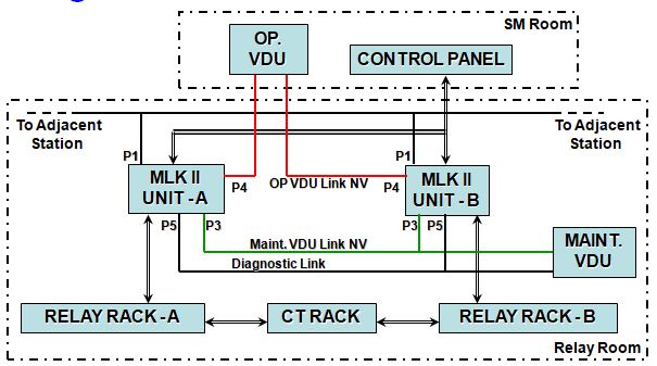
On the basis of requirement of installation / site, MLK II is connected with the peripheral equipments such as VDUs and another MLK II units.
All the peripherals are connected with MLK II with serial communication cable.
I/O from / to control panel are connected through multi core cables.
Design of Relay Room Floor Plan
Once calculation of boards, relays and MLK II configuration is finalized Design of Relay Room Floor Plan is taken up with following criterion:
* MLK II Rack: Size: 2100 mm (l) X 800 mm (w) X 600 mm (d)
Capacity: 2 Cardfiles
* Relay Rack: Size: 2100 mm X 1120 mm X 300 mm
Capacity: 96 Relays
* Termination Rack: Size: 2100 mm X 700 mm X 300 mm
Capacity: 12 Non-vital boards
All the required details now available to design Interface drawings
A typical Interface Drawings consist of:
1. Index
2. Symbols
3. Material List
4. Cable & Wire Details
5. Card file & Keying Plug Location Non-Vital
6. Card file & Keying Plug Location Vital
7. Configuration drawing
8. Serial Ports wiring details
9. Address select PCB, Jumper settings and Keying plug details
10. CPU & PS PCB wiring detail
11. I/O Bit charts
12. Non-vital & Vital board wiring
13. All field gear driving circuit
14. Power supply distribution drawing
15. Fuse chart
16. Rack assembly drawings
17. Interconnection details
18. Contact analysis


pl.
Sent me hitachi EI equipment interlocking details.
ok thanks
what is Bit chart , would you explain about this ?
collection of vital output, vital input & non vital IO bits of all field gears in the SIP arranging in standard form is known as bitchart
We will be need cpu & cpu card for railway signaling sysyem for bangladesh railway
We will be need cpu board & cpu card for railway signaling system